Properties of Detector Description
This pages documents and defines the properties that are part of the detector description
Antennas
Position: - ant_position_{x,y,z}`: The x, y, and z position of the antenna feed point relative to the station position
Orientation:
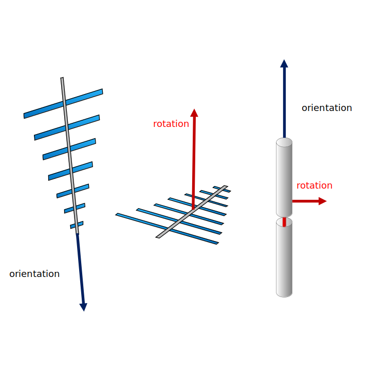
The orientation of the antenna is described with 2 unit vectors. The first vector (referred to as ‘orientation’) defines the orientation of the antenna. The second vector (referred to as ‘rotation’) defines the rotation around the orientation. The vectors are each described by two angles. The theta angle defines the vectors like a zenith angle (0deg is the zenith, 180deg is straight down) and the phi angle defines the azimuth angle (counting from East counterclockwise). Please note that the rotation vector has to be perpendicular to the orientation vector.
For LPDAs, the orientation vector (ant_orientation_theta and ant_orientation_phi) defines the boresight direction (the main sensitivity direction, see sketch below). The rotation vector (ant_rotation_theta and ant_rotation_phi) is perpendicular to the antenna tines and points into the same direction as the connector of the create LPDAs. For dipoles, the orientation vector is parallel to the rod, the rotation vector can point in any direction that is perpendicular to the first vector because of the radial symmetry of dipoles. The user must specify both the orientation vector and the rotation vector. See the illustration of the two vectors for an LPDA and dipole.
Here are a few examples.
1. For an LPDA, the following points the LPDA straight down, with tines aligned with (parallel to) the x-axis (i.e. the east-west direction), and therefore the orientation vector points northwards.
orientation_phi = 0
orientation_theta = 180
rotation_phi = 90
rotation_theta = 90
For an LPDA, the orientation vector is along the boresight direction, and so to point the antenna downward, we specify orientation_theta=180. Because the antenna is completely pointed down, orientation_phi can be any value, so we specify 0 for simplicity. Because the orientation vector points down (orientation_theta = 180), and because the rotation vector is perpendicular to the orientation vector, we must specify the rotation vector to point sideways, and so we set rotation_theta = 90. Finally, to orient the tines correctly: the rotation vector is in the plane perpendicular to the tines, so we must rotate by 90 (rotation_phi = 90) to have the tines themselves be aligned with the x-axis.
2. For a dipole, the following specifies a traditional “upright” dipole.
orientation_phi = 0
orientation_theta = 0
rotation_phi = 0
rotation_theta = 90
For an dipole, the orientation vector is along the rod direction (i.e., going vertically through the cones). Because we want the antenna to be vertical, we set orientation_theta=0. Because the antenna is completely vertical, orientation_phi can be any value, so we specify 0 for simplicity. Because the orientation vector points vertically (orientation_theta = 0), and because the rotation vector is perpendicular to the orientation vector, we must specify the rotation vector to point sideways, and so we set rotation_theta = 90. Because the dipole is azimuthally symmetric, we can fix rotation_phi to any value, and choose 0 for simplicity.
Antenna positions can be visualized in 3D using the script NuRadioReco/detector/visualize_detector.py my_detector.json
Additionally, for the antenna, the user must specify
deployment_time: the time of antenna deployment aka the time when the antenna depth was measured (relevant because the depth changes because of snow accumulation)
type: the type of antenna. A list of available antenna types and their descriptions is given here
Further Discussion on Antenna Coordinates
In principle, the orientation of the antenna is uniquely defined by the three Euler angles. However, the Euler angles are relatively un-intuitive in everyday use. The solution was instead to specify the antenna orientation with two orthogonal vectors that are more intuitive, and that together over-determine the three Euler angles, and therefore, the antenna orientation.
orientation_phi is roughly the equivalent of the first Euler angle, the rotation around the z-axis. orientation_theta is roughly the equivalent of the second Euler angle, the rotation around the x’-axis. rotation_theta and rotation_phi together specify the third Euler angle, the rotation around the z’’-axis. (Here referring to the intrinsic Euler angle definition in the z-x’-z’’ convention).
ADC Table
We document here the properties that are part of the analog-to-digital converter (ADC) description.
adc_nbits: the number of bits of the ADC
adc_min_voltage, adc_max_voltage: the voltage range in volts which is divided by 2**(adc_nbits)-1 to determine the voltage resolution
adc_sampling_frequency, the sampling frequency in GHz
If the user wants to use an ADC for triggering but wants to keep the analog voltage waveforms or wants to use a different ADC for saving the channel data, the following properties can be used:
trigger_adc_nbits: the number of bits of the ADC for the trigger ADC
trigger_adc_min_voltage, trigger_adc_max_voltage: the reference voltage in volts for the trigger ADC
trigger_adc_sampling_frequency, the sampling frequency in GHz for the trigger ADC